
Single Pass Shadow in Webgl
I was wondering whether there was a way to generate omnidirectional shadow in WebGL in an easily understandable way. After some failed experiments, I managed to generate omnidirectional shadows in a single pass. Below I will explain how, and I will show a list of benefits and limitations.
Shadow
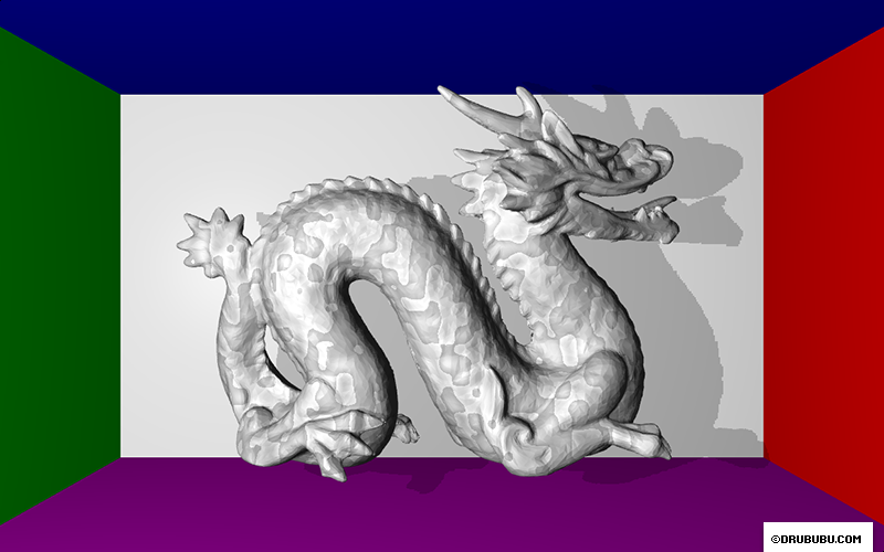
To calculate shadow, you need to know whether a light source is visible from a certain position. If the ray from a position to a light source is obstructed in any way, the position will cast a shadow. In 3D, a model is most likely represented by polygons. All polygons together result in, for instance, a teapot. See the image below.
To calculate whether a position casts shadow, you check whether there
are one or more polygons are between the light source and the
position. This requires a many calculation since you need to check all
polygons, which may be hundreds, thousands or even more.
Although you can optimize this process, it will always remain an intensive
calculation process that must be preformed for all positions in your
scene, preferrably 60 times a second.
You can't store polygons on a GPU in WebGL directly, so this solution doesn't work. You could use JavaScript for this purpose, but it's relatively slow.
Voxels
A voxel is a volume element in a regular three-dimensional grid, most likely a grid with cubes, but any other regular shape is fine as well. Voxels are used in games like Minecraft.
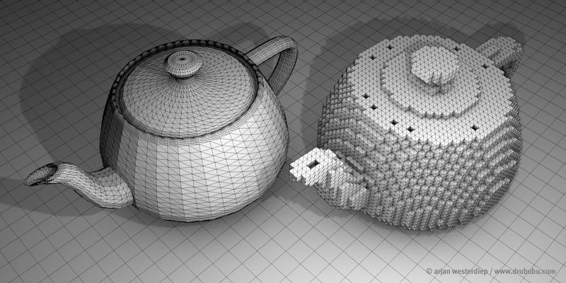
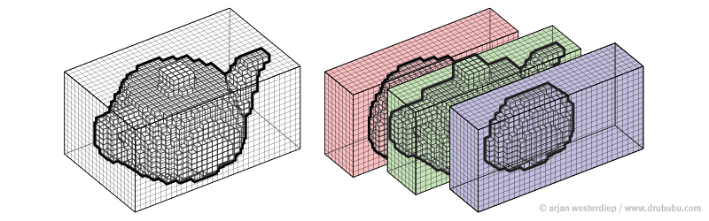
In the image below, a voxel is represented by a cube. On the left, you
see the 3D polygon model of the Utah teapot, on the right the voxel
version of the polygon model.
The 3D model is divided into small
cubes/voxels. If (a part of) a polygon is inside the space occupied by
a voxel, the voxel is visible and shows as a cube.
This tutorial does not cover voxel model generation.
You can convert your 3D model on this website via voxelizer page.
Voxels and Arrays
To calculate shadow, you don't need to visualize voxels, you just need
to know whether a position is occupied or not. Instead of a cube, the
only value you need is true - occupied - false - not occupied - and
store this value in a multidimensional array.
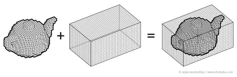
The horizontal,
vertical and depth dimensions of the array are equal to the distance
between the minimum and maximum positions of the voxel model.
The
minimum and maximum positions represent the bounding box of the model.
This bounding box is used to check whether a ray intersects with the
bounding box.
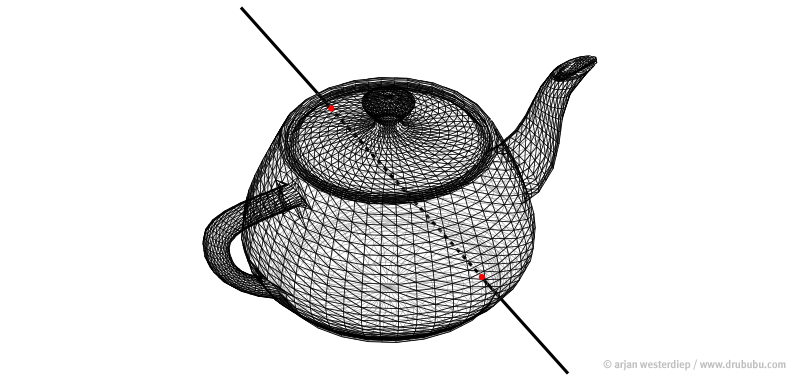
To check whether the ray intersects with the model, you need to calculate whether the ray intersects with the bounding box. The shadow calculation is now reduced to a very few calculations.
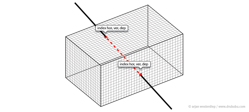
If the ray intersects with the bounding box, the intersection positions are converted into array indexes. All you need to do next, is traverse the array from the start to the end index. If an index has the value true - occupied - we can stop; there's a voxel between the start and end position of the ray that prevents the start position from being lit by a light source. You can stop your calculations here; there's no need to calculate any other occupied voxel positions in the multidimensional array.
If the ray starts or ends inside the bounding box, the array indexes of the bounding box are corrected, so self-shadowing can be calculated as well.
Line traversal
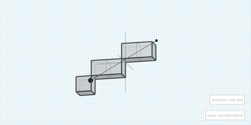
Ideally, you want to traverse all relevant array indexes; the ray
should be fully encapsulated by voxels.
James McNeill wrote an
interesting tutorial Raytracing on a grid about how this can be done.
The following interactive application shows the result.
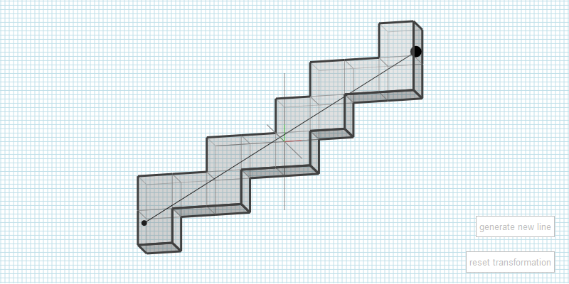
Although the algorithm works perfectly fine, I didn't use it, since it was not ideal for GPU usage. The next, faster - however less precise - line traversal algorithm is used. It involves less code and no if- statements, which slows down the GPU.
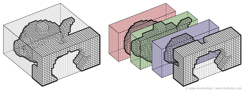
Line Box intersection
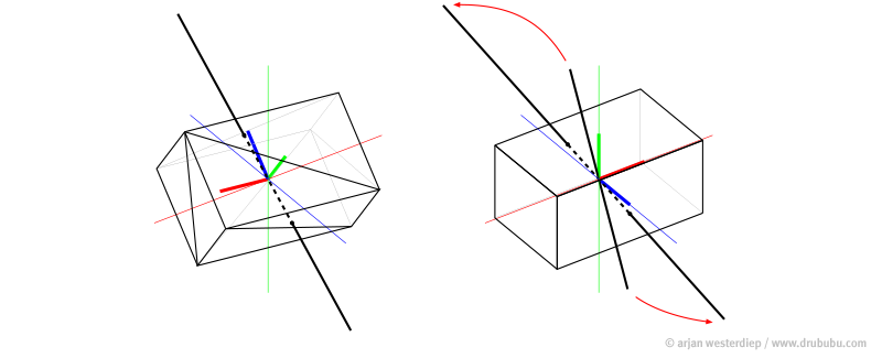
To calculate the ray bounding box intersection, I have used two methods.
The first one rotates the bounding box (left image). 12 polygons represent the bounding box and for each polygon a ray-polygon intersection is calculated.
To speed up the calculations, I switched
over to a so-called axis aligned bounding box or AABB (right
image).
The bounding box is not rotated but aligned to the x, y
and z axis. The ray is rotated by a so called inverse transformation.
This is the inverse of the transformation which is used in the first
approach to transform (rotate) the bounding box.
Using an axis
aligned bounding box reduces the number of calculations dramatically,
while the result is the same.
Arrays and Textures
Since WebGL does not support arrays, a texture is used to mimic an array.
Generally speaking, a texture is used as a picture but you can also use a texture for storing data for any purpose other than visual.
For this application, a .png or 'ping' is used. .png stands for
'Portable Network Graphics'.
PNG supports various options for
storing data. In this case, 32 bits are ideal.
32 bits represent 4
channels; a red, green, blue and an alpha channel. Each channel has 8
bits.
For each channel, 8 positions can be stored.
The
channels are not strictly separated from each other, they are just a
collection of bits.
The next table shows the information each bit contains.
The value of a bit is either 1 - occupied - or 0 - not occupied.
| red channel | |
| bit 0 | = depth position ( offset* + 0 ) |
| bit 1 | = depth position ( offset* + 1 ) |
| bit 2 | = depth position ( offset* + 2 ) |
| bit 3 | = depth position ( offset* + 3 ) |
| bit 4 | = depth position ( offset* + 4 ) |
| bit 5 | = depth position ( offset* + 5 ) |
| bit 6 | = depth position ( offset* + 6 ) |
| bit 7 | = depth position ( offset* + 7 ) |
| green channel | |
| bit 8 | = depth position ( offset* + 8 ) |
| bit 9 | = depth position ( offset* + 9 ) |
| bit 10 | = depth position ( offset* + 10 ) |
| bit 11 | = depth position ( offset* + 11 ) |
| bit 12 | = depth position ( offset* + 12 ) |
| bit 13 | = depth position ( offset* + 13 ) |
| bit 14 | = depth position ( offset* + 14 ) |
| bit 15 | = depth position ( offset* + 15 ) |
| blue channel | |
| bit 16 | = depth position ( offset* + 16 ) |
| bit 17 | = depth position ( offset* + 17 ) |
| bit 18 | = depth position ( offset* + 18 ) |
| bit 19 | = depth position ( offset* + 19 ) |
| bit 20 | = depth position ( offset* + 20 ) |
| bit 21 | = depth position ( offset* + 21 ) |
| bit 22 | = depth position ( offset* + 22 ) |
| bit 23 | = depth position ( offset* + 23 ) |
*offset = sprite * 24 ('sprite' is explained below)
In the end, only the red, green and blue channels are used to provide
position information; 24 bits in total.
The alpha channel of 8
bits is not used for providing position information, but for
calculating the minimum distance from a occupied position in the red,
green and blue channel.
The alpha channel has 8 bits, limiting the amount of data storage to
integer values between 0 and 255.
The lower 4 bits are used for
calculating the minimum distance ( 0 - 15 ) of the lower 12 positions
and the upper 4 bits are used for the minimum distance ( 0 - 15 ) of
the upper 12 positions stored in the texel, a pixel in a texture.
A texel is red and generates a 32 bits value; the red, green, blue and
alpha channel.
A specific bit - representing an array index - in
the array is checked. If the position is not occupied - false - the
alpha channel information is used to skip a certain amount of
redundant - empty - voxels in the array traversal. If you combine all
information in a single texel, the information is always useful;
either the position is occupied or you know the minimum distance to
speed up the process of finding a possible occupied position.
Alternatively, you can store more precise data for the minimum
distance, however you then need a bigger texture and second texel
read.
Notice that the voxel model is solid inside, so an occupied position is found faster (the array traversal may miss some positions due to rounding errors).
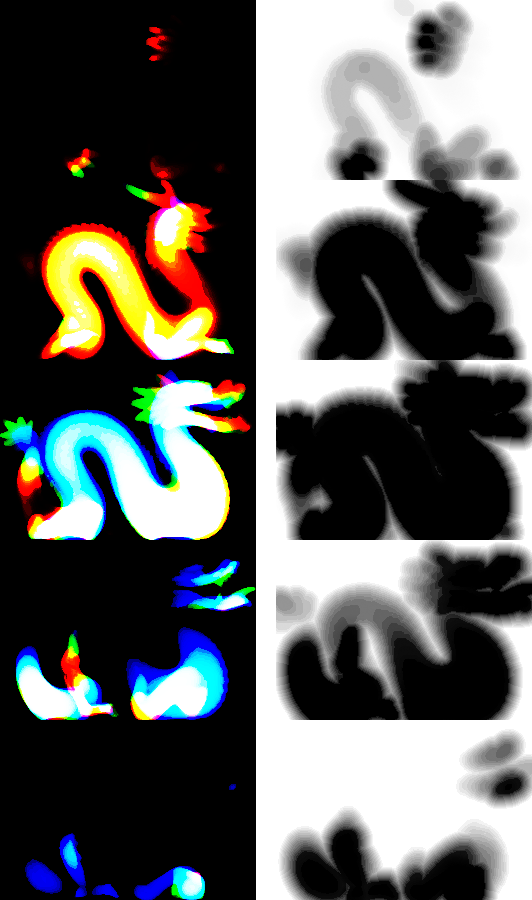
The image shown is small, the object z-dimension fits in 24 bits, what
if your model is bigger?
Use an atlas; multiple images or sprites
combined into one single texture. The lower left sprite in the image
below refers to the first 24 positions, the lower right sprite refers
to position 24 to 47, and so on.
Keep in mind that most GPUs like pot textures. Pot is short for Power
of Two. The size must be 2, 4, 8, 16, 32, 64, 128, 256 and so on. The
width and height don't necessarily have to be equal, as long as the
width and height are a power of two, e.g. 512 x 256.
You may need some
extra empty space in your texture to meet the pot requirement.
Benefits
- Relatively fast (no map generation, only one (pre-processed) texture).
- Omnidirectional shadow in a single pass.
- Multiple light sources can use the same (static) data.
Limitation
- Technique only works for objects with a static mesh (scaling, rotation and translation are not a problem).
- Multiple texel reads per fragment.
- The texture dimensions must meet the power of two requirement; the next possible texture dimension is twice as big.
- Limited to one, possibly a few, static objects in WebGL.